FaxPress Premier WebHelp: Admin Guide > Appendix > Hardware Upgrade > Digital T1 Upgrade
|
Digital T1 Upgrade
 Other Related Topics...
Upgrade options are determined by the number of fax boards currently installed in the unit:
FaxPress Premier Digital T1 units with 1 board factory-installed support 1 T1 line (24 fax channels if T1 CAS, 23 fax channels if T1 ISDN PRI.) These units can be upgraded with:
|
■
|
1 additional board, to support 2 T1 lines (48 T1 CAS fax channels, 46 T1 ISDN PRI fax channels.) |
|
■
|
2 additional boards, to support 3 T1 lines (72 T1 CAS fax channels, 69 T1 ISDN PRI fax channels.) |
FaxPress Premier units with 2 boards factory-installed support 2 T1 lines (i.e., 48 channels if CAS, 46 if ISDN PRI.) These units can be upgraded with 1 board, to support 3 T1 lines (i.e., 72 channels if CAS, 69 if ISDN PRI.)
FaxPress Premier units with 3 boards factory-installed support 3 T1 lines (72 T1 CAS fax channels, 69 T1 ISDN PRI fax channels.) Units with 3 boards installed support the maximum number of fax channels avilable with the FaxPress Premier Digital, and cannot be upgraded with additional fax boards.
These upgrade procedures assume that your FaxPress Premier is running the latest software build (at least version 4.0). To update your server software, visit the Castelle FTP site.
Required Upgrade Procedures
Upgrading the FaxPress Premier Digital T1/ISDN PRI involves three steps:
|
1.
|
Adding the T1/ISDN PRI board(s) to the FaxPress Premier, as described in . |
|
2.
|
Configuring the new board(s). See . |
|
3.
|
Updating the software so your hardware will work properly, as described in . |
These steps must be completed for the upgraded FaxPress Premier Digital server to be operational.
Required Tools
T1/ISDN PRI fax board upgrades require a Phillips head screwdriver and needlenose pliers.
Upgrade Kit Contents
When you unpack your FaxPress Premier Upgrade Kit, make sure it contains the following components:
|
■
|
1 or 2 Intel Dialogic Intelligent Fax Board(s) |
|
■
|
1 Castelle Upgrade Distribution CD |
|
■
|
1 CT (ribbon) bus cable, if upgrading from 1 T1/ISDN PRI board to 2 or 3 T1/ISDN PRI boards |
Adding a T1 Fax Board to the FaxPress Premier
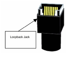
T1 lines disconnected from an active device or loopback jack for more than 15 minutes will fail Central Office loopback tests, and the Central Office will then cut off service. Typically the customer is charged to restart the service. Make sure you use the loopback jacks as described below in step 1 to prevent this from happening.
Each fax board added will increase the number of supported channels by 24 if the T1 signaling protocol is CAS E&M, 23 if the T1 signaling protocol is ISDN PRI.
To install an additional T1 board in the FaxPress Premier Digital, follow these steps:
|
1.
|
Disconnect the T1 line or lines from the FaxPress Premier, and plug one of the Castelle-provided loopback jacks (shown below) into the connector at the end of each disconnected T1 line. This will prevent the T1 carrier from cutting off service to the T1 lines. |
|
2.
|
Discharge static electricity from yourself by touching a grounded surface, attach a grounded static-dissipative wrist strap, and make sure the working sur-face is static-dissipative and grounded. |
|
3.
|
Shut down the FaxPress Premier by accessing the System Information folder in the System & Diagnostics folder. Right-click in the blank area of the list to the right side of the Faxmain window, and choosing the System Shutdown command. |
|
4.
|
Disconnect the power cord from the unit. |
Make sure the 8-digit serial number displayed on the left side of the label on the CD (for example, S/N 84100200) matches the serial number on the label on the bottom of your FaxPress Premier server (for example, SERIAL NO. 84100200). If the serial number doesn’t match, contact Castelle tech support immediately. If you are upgrading more than one FaxPress Premier, use the correct upgrade CD for each server, or the software upgrade will fail.
|
5.
|
Remove the 5 cover screws holding the cover of the FaxPress Premier to the back panel, the 3 screws holding the bottom of the cover to each side of the chassis, and the 2 screws holding the front edge of the cover under the lip at the top of the front panel. The screw directly above the thumbscrew for the fan unit cover does not need to be removed, but you may need to loosen it slightly, as shown below. |

Remove only the FaxPress Premier cover screws. Do not remove any other chassis screws.
|
6.
|
Remove the cover by sliding it toward the rear of the FaxPress Premier, then lifting it upwards when it is free of the front panel lip. |
|
7.
|
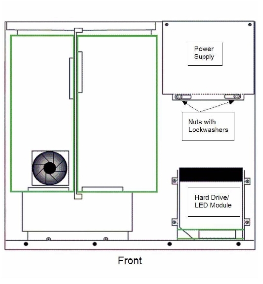
Locate the power supply module in the FaxPress Premier chassis as shown below. |
|
8.
|
Remove the 2 nuts with lock washers that hold the power supply to the base of the FaxPress Premier chassis. You may need to use needlenose pliers for this task. |
|
9.
|
Remove the 2 rear panel screws that hold the bottom portion of the power supply to the rear panel of the FaxPress Premier.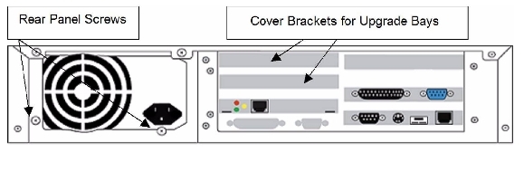 |
|
10.
|
Move the power supply to the side of the chassis, as far as the cables will allow. |
|
11.
|
Locate the cover brackets covering the bays above the factory-installed T1/ISDN PRI board(s), as shown above. |
|
12.
|
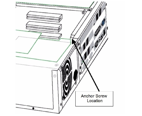
Remove the Phillips screw anchoring the cover bracket and remove the cover bracket from the lower bay, if this bay is not occupied by a board. If the lower bay is occupied by a board, remove the Phillips screw that is anchoring the cover bracket for the upper bay, and remove that cover bracket. |
|
13.
|
Remove the upgrade board from its packing material. Discharge static electricity from yourself by touching a grounded surface, attach a grounded static-dissipative wrist strap, and make sure the working sur-face is static-dissipative and grounded. Take care not to touch the connector tabs; hold the circuit board by the black metal mounting bracket, the metal faceplate with the analog line connectors, or the edges of the board. |
|
14.
|
Align the board so the black metal end-bracket angles UP from the board. This will mean that the piggyback board is on the top of the main board, as shown below.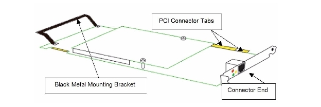 |
|
15.
|
Engage one end of the black metal mounting bracket (the end the arrow above is pointing to) in the card guide, then lower the connector end of the board and slide the board into place, aligning the PCI connector tabs so they plug into the PCI slot on the chassis smoothly and firmly. |

Replace the anchor screw, to hold the upgrade board firmly in place. If only one T1/ISDN PRI board was factory-installed in the chassis, install the ribbon bus cable supplied with your upgrade kit on that existing T1/ISDN PRI board, and then connect it to the upgrade board you have added, attaching it to the connectors shown in the figure below.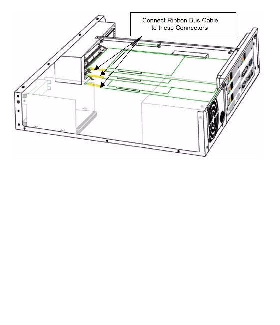
|
16.
|
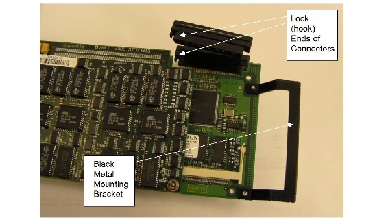
Make sure you install the ribbon bus cable with the lock (hook) ends of the connectors toward the BACK PANEL of the FaxPress Premier chassis, as shown in the figure below. This orientation will mean that the hooks are on the ends of the connectors that are AWAY from the Black Metal Mounting bracket, as shown. |
|
17.
|
To add two upgrade boards, connect the ribbon bus cable to both of the new fax boards. |
|
18.
|
If two boards were factory-installed prior to this upgrade, the ribbon bus cable will be in place; simply push the appropriate cable connector onto the board connector of the new board. Press the connectors firmly into place, to make sure there is a solid connection. |
|
19.
|
Replace the power supply in the FaxPress Premier chassis. |
|
20.
|
Replace the 2 rear panel screws that hold the bottom portion of the power supply to the rear panel of the FaxPress Premier, and then replace the 2 nuts with lock washers that hold the power supply to the base of the chassis. |
|
21.
|
Slide the FaxPress Premier cover back into place, making sure the leading edge fits under the front panel lip. |
|
22.
|
Replace the cover screws, keeping in mind that there are 5 for the back panel, 3 along the bottom of each side, and 3 holding the leading edge under the front panel lip. Tighten the fourth front panel lip screw if you loosened it. |
The new board is now ready to be connected and configured for service.
To add a second or third fax board, go through the steps again, starting from Step 10.
Configuring the Dialogic System Software
After adding the new fax board or boards as described in , and after connecting all necessary cables to the unit, follow these steps to configure the FaxPress Premier:
|
1.
|
Access the FaxPress Premier server by connecting a keyboard, mouse, and monitor to it. |
This task cannot be performed remotely. The unit must be accessed using a keyboard, mouse and monitor.
|
2.
|
Power up the FaxPress Premier. A message box may appear briefly, telling you that the new board has been detected. This will only occur the first time you upgrade. |
For Windows 2003, please wait approximately 1 minute before continuing. This ensures that all fax boards are fully detected.
|
3.
|
In the Found New Hardware Wizard dialog box, select Press . |
|
4.
|
In the next Found New Hardware Wizard dialog box screen, select . Press . |
|
5.
|
In the dialog box, press Yes. |
|
6.
|
The Completing the Found New Hardware Wizard dialog box appears. Press . |
|
7.
|
If you have installed more than one board, you will be prompted again to install new hardware. In that case, repeat steps 3 thru 6 for each additional board. Once you are done, proceed to the next step. |
|
8.
|
Select the Start>Programs>Administrative Tools>Services menu option to access the Services Folder. |
|
9.
|
Expand the column of the services list so you can read the full names of the services, then scroll to . Right-click on this service. |
|
10.
|
Stop the by selecting the Stop option. The Stop Other Services dialog box opens. |
|
11.
|
Click the button. If you see error messages regarding application or memory errors, click in each message box. This will stop other active FaxPress Premier services. |
|
12.
|
Stop the following additional services manually by right-clicking each one and then selecting the option: |
|
■
|
Castelle FaxPress Startup/Monitor Process |
|
■
|
GammaLink System Service |
|
13.
|
When all Castelle FaxPress Premier services are stopped, open the Start menu and choose: |
|
14.
|
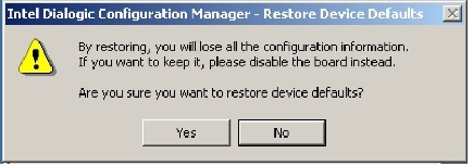
Click in the dialog box shown below. |
|
15.
|
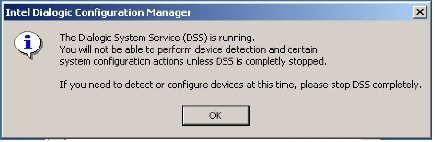
In the Intel Dialogic Configuration Manager window, click the [Stop] red button to stop the DCM Service, then right-click onand select to make the system rescan the boards. 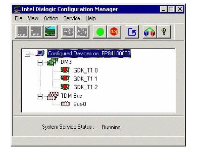 |
|
16.
|
Click in the dialog box shown below. |
|
17.
|
During the detection process, the Assign Firmware File window opens, and displays a list of .pcd files, as shown below.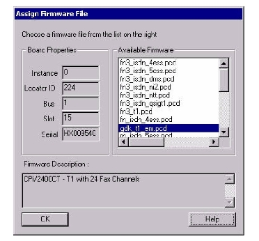 |
|
18.
|
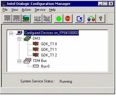
For configuring a T1 board, find the gdk_t1_em.pcd file in the list, select it, and click OK. The software scan of the boards continues until complete. Then the Intel DCM window reappears, with all of the boards listed, and a red light displayed in each device icon, as shown on the next page. |
All boards should use the same .pcd file.
|
19.
|
Repeat step 13 for each additional fax board installed in the FaxPress Premier. |
|
20.
|
Select the first board (for example, GDK_T1 0 in the Figure above), and then click the green Start Service button in the menu bar. A progress bar appears on top of the background screen indicates the progress of the service startup. When all boards are started (all of the lights in the device icons are green), click and set it from to , then select the File>Exit command. |
|
21.
|
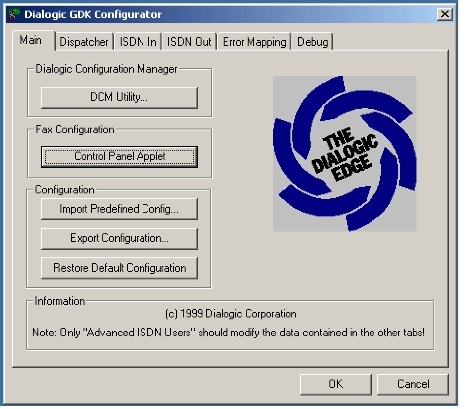
Click the Start Menu and select: |
Programs>Intel Dialogic System Software>Configure GDK
to open the Dialogic GDK Configurator window, as shown on the next page.
|
22.
|
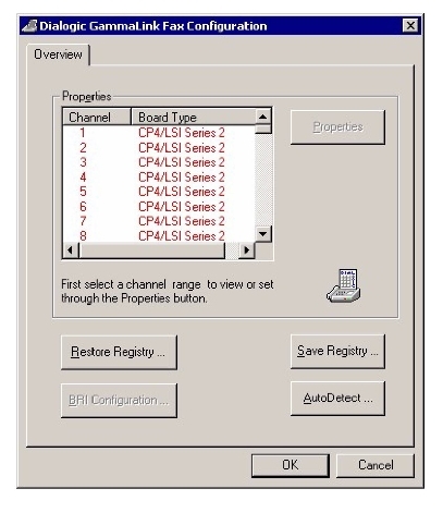
In the Fax Configuration section, click the button. The Dialogic GammaLink Fax Configuration window appears. See the figure above. |
|
23.
|
Click the button. A warning message appears. |
|
24.
|
Click . When the auto-detection process is complete, a message box appears, indicating that all boards have been detected. |
|
25.
|
Clickin the message box. The Dialogic GammaLink Fax Configuration window now displays the new number of supported fax channels, as shown below. |
|
26.
|
Verify that this number is correct. Then click to exit the Dialogic GammaLink Fax Configuration box. |
|
27.
|
Click the button in the Configuration section of the Dialogic GDK Configurator window. The Open Profile dialog box appears, with the Registry Profile Files (.prf files) as shown below.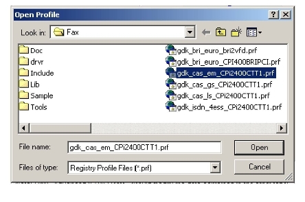 |
|
28.
|
Select the .prf that matches the T1 line you have connected to the new T1 board (for example, gdk_cas_em_CPi2400CTT1.prf for a T1 board), then click . |
If you select the wrong profile file, the fax board’s behavior will be unpredictable. To correct this mistake, complete Step 21, and when the Dialogic GDK Configurator window opens, click the Import Predefined Configuration button again, and repeat Steps 19 and 20, selecting the correct profile file.
|
29.
|
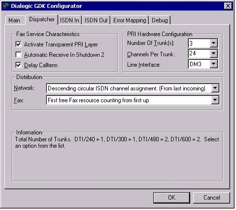
A dialog box asks how many trunks. Use the pull-down menu to select the total number of trunk lines that are now supported by the FaxPress Premier (each board supports one trunk line; if you now have 3 T1/ISDN PRI boards installed in your FaxPress Premier, it supports 3 trunk lines), and then click OK. The Dialogic GDK Configurator window appears. |
|
30.
|
Click the Dispatcher tab in the Dialogic GDK Configurator window, and look in the section of the tab, at the now supported, as shown below. |
|
31.
|
Verify that the in the section is correct. In the example above, 3 trunks are supported, which means 3 T1/ISDN PRI boards are now installed and configured. Click OK to close the window. This completes the T1/ISDN PRI board configuration. Next, go on to the final section, |
Running the FaxPress Premier Upgrade Software
To complete the upgrade and configure the FaxPress Premier for use with the new board, follow these steps:
|
1.
|
On a local Windows PC on the same network as the FaxPress Premier server, create a shared folder that allows access to everyone on the local network. |
|
2.
|
Place the distribution CD that was supplied with your upgrade kit in a CD drive on this local PC. |
Make sure the 8-digit Serial Number displayed on the left side of the label on the CD (for example, S/N 84100200) matches the Serial Number on the label on the bottom of your FaxPress Premier server (for example, SERIAL NO. 84100200). If you are upgrading more than one FaxPress Premier, use the correct upgrade CD for each server, or the software upgrade will fail.
|
3.
|
Copy the file FPPUpgrade.exe from the distribution CD to the shared folder on this local PC. |
|
4.
|
Log into the FaxPress Premier server; either by means of a directly connected monitor, keyboard, and mouse; or by means of a remote Windows PC with network access. |
|
5.
|
Using Microsoft Explorer, browse in My Network Places to locate the shared folder. |
|
6.
|
Copy the file FPPUpgrade.exe from the shared folder to the C:/Castelle directory on the FaxPress Premier. |
|
7.
|
Right-click on the file, and select Properties. In the Properties dialog box, uncheck the Read-only checkbox, so the file becomes Read-Write. |
|
8.
|
Reboot the FaxPress Premier. This runs FPPUpgrade.exe, and then automatically deletes this file. |
|
9.
|
By means of a remote Windows PC with network access, log into the FaxPress Premier server as Administrator. |
|
10.
|
Expand the FaxPress Neighborhood tree to show the Administration branch, select Fax Lines, and look at the list of lines to verify that the total number of fax channels has increased to reflect your upgrade. If you are configuring for an ISDN PRI/PRI board, disable the last three channels in the Fax Lines menu. |
|
11.
|
Test each new channel; send a fax over one of the channels you added. |
This completes the upgrade procedure. The upgraded FaxPress Premier Digital is now ready for use.
If you have any questions, please contact Tech Support at 408-852-8080 or visit the Castelle web site.
 You Should Also Read...
FaxPress Premier WebHelp
Last Updated: 11/1/2007
E-mail this page
|
Castelle
855 Jarvis Drive, Suite 100
Morgan Hill, CA 95037
Toll-free 800.289.7555
Tel 408.852.8000
Fax 408.852.8100
www.castelle.com
|